Mux-mode protocol (advanced)
This page describes CANmod.router mux-mode in detail.
Note
When using software tools supporting mux-mode, knowing details regarding the implementation of mux-mode is not required. Find tools supporting mux-mode on csselectronics.com.
The information on this page can be used to gain a better understanding on how mux-mode works and how to develop custom tools supporting mux-mode.
In mux-mode, traffic is routed between CAN-P and CAN-S using two tunnels: the P-to-S and the S-to-P tunnel. The CANmod.router configuration defines a set of message IDs assigned to the tunnels. A user (CAN-bus node) connected to the CAN-P bus can communicate with all CAN-S buses through the tunnels as if directly connected to each bus.
P-to-S tunnel
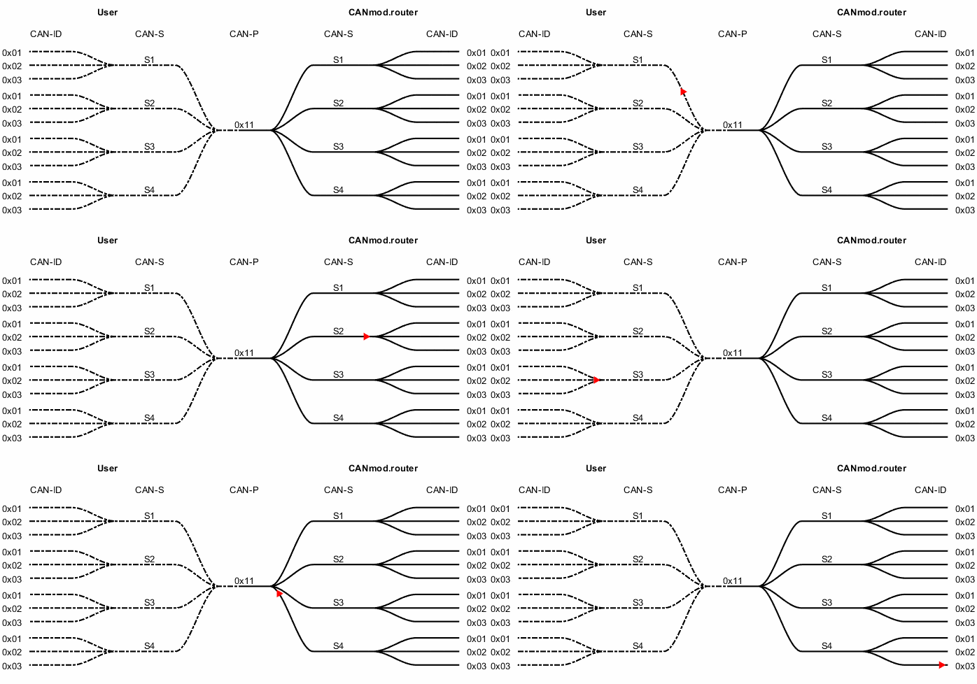
The P-to-S tunnel transfers data from the CAN-P bus to the CAN-S buses (e.g. transmission requests). Below figure illustrates how traffic is generated and muxed by the user software tool (dashed lines), transmitted through the P-to-S tunnel on CAN-P, received and demuxed by the CANmod.router, and placed on CAN-S.

The P-to-S tunnel. Data to CAN-S (S1-S4) is routed through the CAN-P bus (on ID 0x11). The dashed lines represent the muxing performed by the user software tool.
S-to-P tunnel
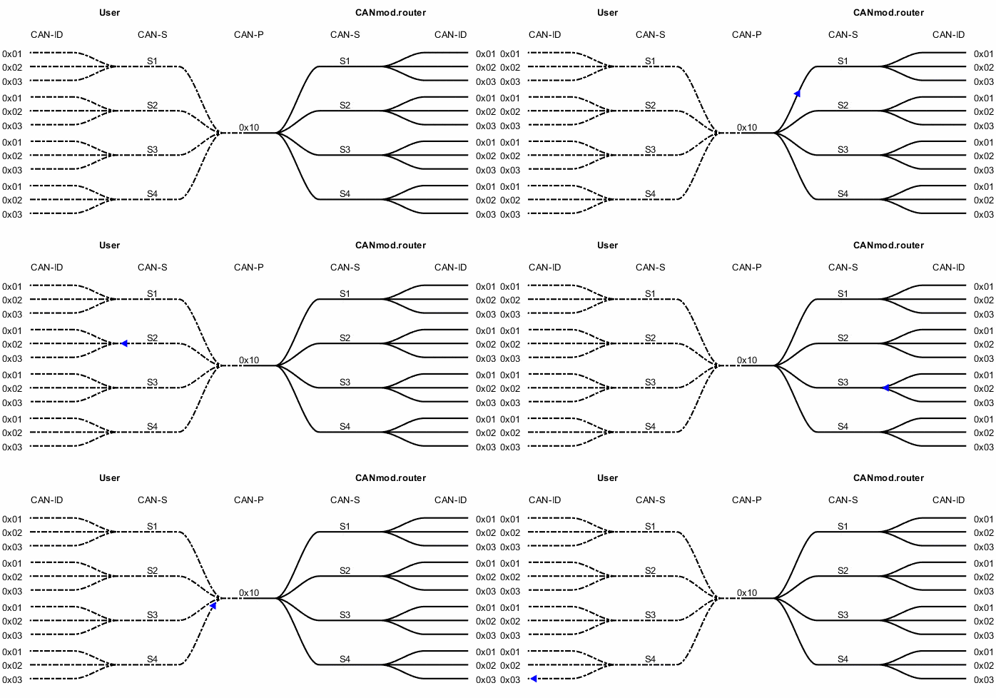
The S-to-P tunnel transfers data from CAN-S (e.g. received messages, transmission acknowledgments, and error frame events) to CAN-P. Below figure illustrates how traffic is received on CAN-S, muxed by the CANmod.router, transmitted on CAN-P, received by a user CAN-bus node, and demuxed by the user software tool (dashed lines). Once demuxed by the user, the original traffic on CAN-S is restored.

The S-to-P tunnel. Data from CAN-S (S1-S4) is routed through the CAN-P bus (on ID 0x10). The dashed lines represent demuxing by the user software tool.
Protocol
This section describes in detail how traffic to/from CAN-S is transported on CAN-P using only a few message IDs.
Below figure illustrates the protocol stack. Each layer of the stack is explained in detail below.
Protocol stack. The dashed part of the stack is implemented by the user software tool.
Packaging
Bus traffic is packaged such that it can be transferred as message payloads and restored by the receiver. Below table lists how the different frame types are packaged.
Byte |
0 |
1 |
2 |
3 |
4 |
||||||||||||
|---|---|---|---|---|---|---|---|---|---|---|---|---|---|---|---|---|---|
Bit |
7-5 |
4 |
3 |
2-0 |
7 |
6 |
5 |
4 |
3 |
2 |
1 |
0 |
7-0 |
7-0 |
7-0 |
||
CB |
ch |
xtd(0) |
fd(0) |
dlc |
tx |
rtr |
0 |
0 |
id |
- |
|||||||
CE |
ch |
xtd(1) |
fd(0) |
dlc |
tx |
rtr |
id |
||||||||||
FB |
ch |
xtd(0) |
fd(1) |
dlc |
tx |
brs |
0 |
0 |
id |
- |
|||||||
FE |
ch |
xtd(1) |
fd(1) |
dlc |
tx |
brs |
id |
||||||||||
ER |
ch |
0 |
0 |
1 |
1 |
1 |
error-type |
- |
|||||||||
ch: Channel index0= S11= S22= S33= S4
xtd: Extended ID framefd: FD framedlc: DLCtx: Transmission acknowledgementrtr: Remote transmission requestbrs: Bit-rate-switchID: Identifiererror-type:0: BIT1: ACK2: Form3: Stuff4: CRC5: DLC (must always be in range 0-8 forCBandCEframes)6: Bus-off recovery[1]255: Other
To optimize throughput on CAN-P, the CANmod.router can pack several frames in one payload.
Note
The ESI flag is ignored when packaging CAN-FD messages.
Transport
The packaged payload (containing one or more of the original frames) can be larger than what can be carried by a single message frame. By using a transport layer, it becomes possible to transport big payloads across multiple frames. The CANmod.router transport layer uses a subset of the frames defined by ISO 15765-2 (commonly referred to as ISO-TP). The ISO-TP addressing modes used are Normal-11-bit and Normal-29-bit.
The transport layer frames types are listed in below table.
Byte |
0 (7-4) |
0 (3-0) |
1 |
|---|---|---|---|
Single frame standard (SF) |
0b0000 |
DL |
- |
Single frame FD (SF) |
0b0000 |
0b0000 |
DL |
First frame (FF) |
0b0001 |
DL |
|
Consecutive frame (CF) |
0b0010 |
SN |
- |
DL: Data lengthSN: Sequence number (consecutive with wraparound)
Payloads are transmitted using single-frames when possible. Payloads exceeding a single-frame are transmitted using a first-frame followed by one or more consecutive frames. Data payloads are optimized by always using the shortest possible DLC. For DLC 9 to 15, unavoidable padding uses byte value 0xCC.
Examples
Below examples assume that CAN-P bus is set up to use standard CAN (not CAN-FD).
Note
It is possible to route CAN-S CAN-FD traffic on CAN-P using standard CAN.
Example 1: Traffic from the CAN-S interfaces is packaged by the CANmod.router.
The following four message frames are received by the CANmod.router on the CAN-S interfaces:
# |
ch |
xtd |
fd |
dlc |
tx |
rtr |
brs |
id |
payload |
|---|---|---|---|---|---|---|---|---|---|
1 |
S1 |
0 |
0 |
1 |
0 |
0 |
0 |
|
|
2 |
S2 |
1 |
0 |
2 |
0 |
0 |
0 |
|
|
3 |
S3 |
0 |
1 |
3 |
0 |
0 |
0 |
|
|
4 |
S4 |
1 |
1 |
4 |
0 |
0 |
0 |
|
|
The four frames are packaged as described in Packaging:
1:
0087F1012:
311FFFFFF201023:
4987F30102034:
7A1FFFFFF301020304
Concatenated, the payload becomes: 0087F101311FFFFFF201024987F30102037A1FFFFFF301020304 (26 bytes).
The payload now enters the transport layer as described in Transport. As CAN-P is configured to standard CAN (not FD), it is not possible to store the entire payload (26 bytes) in one frame. The transport layer splits the payload into multiple frames using a first-frame followed by one or more consecutive-frames as demonstrated below.
The payload is split into one first-frame followed by 3 consecutive frames.
# |
ch |
xtd |
fd |
dlc |
tx |
rtr |
brs |
id |
payload |
|---|---|---|---|---|---|---|---|---|---|
FF |
P |
0 |
0 |
8 |
0 |
0 |
0 |
|
|
CF1 |
P |
0 |
0 |
8 |
0 |
0 |
0 |
|
|
CF2 |
P |
0 |
0 |
8 |
0 |
0 |
0 |
|
|
CF3 |
P |
0 |
0 |
7 |
0 |
0 |
0 |
|
|
When the four above frames are received by the user, the original traffic from the CAN-S interfaces can be restored.
Example 2: A transmission request (for a specific CAN-S bus) is transmitted by the user on the CAN-P bus.
The user wants to transmit the following message on CAN-S1:
# |
ch |
xtd |
fd |
dlc |
rtr |
brs |
id |
payload |
|---|---|---|---|---|---|---|---|---|
1 |
S1 |
0 |
0 |
1 |
0 |
0 |
|
|
The frame is packaged as described in Packaging:
1:
00C7F101
Note
Note that the tx flag is set.
The payload now enters the transport layer as described in Transport. As the payload is only four bytes, it can fit into a single frame (even when CAN-FD is not used). The single-frame, to be transmitted on the primary bus, becomes:
# |
ch |
xtd |
fd |
dlc |
rtr |
brs |
id |
payload |
|---|---|---|---|---|---|---|---|---|
SF |
P |
0 |
0 |
5 |
0 |
0 |
|
|
By transmitting above message on the CAN-P bus, the user instructs the CANmod.router to transmit the original message on CAN-S1.
Note
If configured to do so, the CANmod.router will respond with a transmission acknowledgement once the message has been successfully placed on CAN-S1.