Explained, pulse
This section describes the channel configuration related to pulse signals.
First, it is explained how pulse signals are digitized using the Digital voltage level thresholds. Then the pulse configurations are explained with examples. Finally, a practical demo combining several configuration options is given.
Digital level
A pulse is counted when the digital level changes from low to high (rising edge). The pulse counting uses the Digital voltage level thresholds (see Explained, digital) to determine when the digital level changes.
Below follows a few examples on how the digital thresholds influence how pulses are counted.
Note
It is important to carefully set the digital thresholds to obtain an accurate pulse count.
Example 1
In below example, the high/low digital thresholds are set to 70% (7 V) and 30% (3 V) respectively. These settings result in a pulse count of 5 (5 transitions from digital low to high).
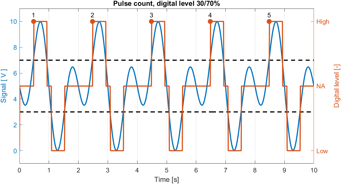
Digital high threshold: 7 V, digital low threshold 3 V. Markers indicate when a pulse is counted.
Example 2
In below example, the high/low digital thresholds are set to 60% (6 V) and 40% (4 V) respectively. These settings result in a pulse count of 10 (10 transitions from digital low to high).
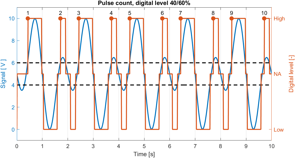
Digital high threshold: 6 V, digital low threshold 4 V. Markers indicate when a pulse is counted.
Example 3
In below example, the high/low digital thresholds are set asymmetrically to 60% (6 V) and 10% (1 V) respectively. These settings result in a pulse count of 6 (6 transitions from digital low to high).
Note
A pulse is only counted when the digital level changes from low level to high level. Two consecutive high levels (separated by a NA / unknown digital state) are considered as one pulse.
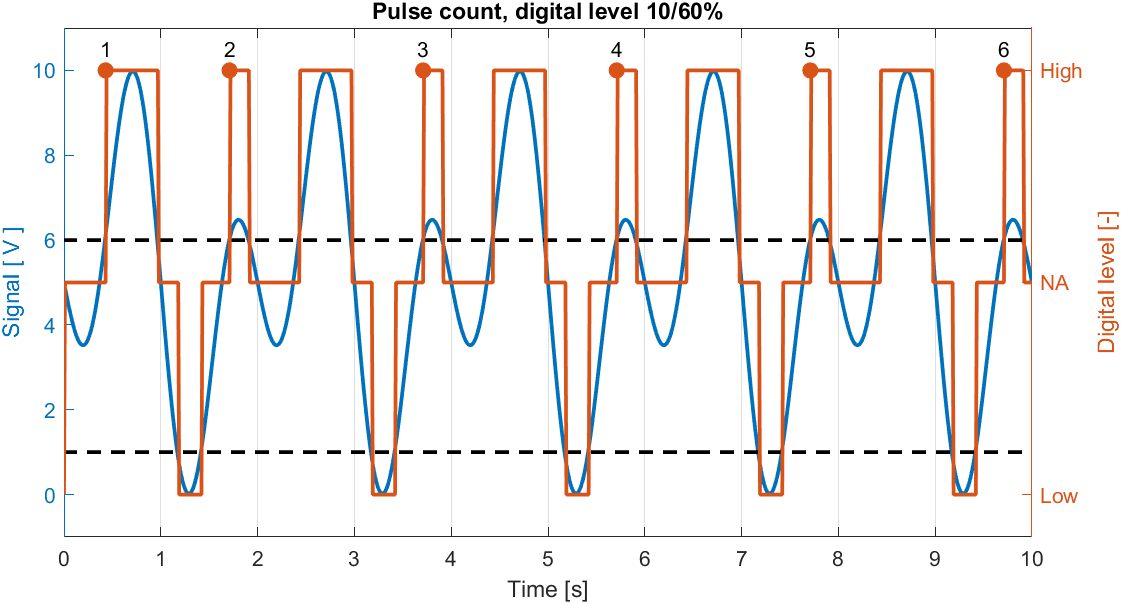
Digital high threshold: 6 V, digital low threshold 1 V. Markers indicate when a pulse is counted.
Mode
The CANmod.input supports the following pulse mode settings:
Normal
In normal mode, pulses are counted on each channel separately. The pulse count can only increase.
Encoder
In encoder mode, two channels (must be a primary/secondary channel pair, 1/2, 3/4, 5/6 or 7/8) are combined to count pulses with direction - i.e., the pulse count can both increase and decrease.
Note
This mode is typically used to measure shaft position and shaft speed using a rotary encoder (see Example 2).
Encoder mode assumes the following pin configuration:
Primary channel (e.g. Channel 1): Pulse signal.
Secondary channel (e.g. Channel 2): Direction signal.
When the digital level of the secondary channel is high, pulses observed on the primary channel increase the count. Contrarily, when the digital level of the secondary channel is low, pulses observed on the primary channel decrease the count.
Note
In this mode, the pulse count result is copied to both the primary and secondary channel outputs. However, by configuring one channel to Accumulate and the other to Reset (see Count) it is possible to output both absolute pulse count (e.g. shaft position) and pulse frequency (e.g. shaft speed).
Example 1
In below example, the direction signal is a simple digital signal.
Initially, the direction signal is high with pulses on the primary channel increasing the counter.
Later, the direction signal goes low with pulses on the primary channel decreasing the counter.
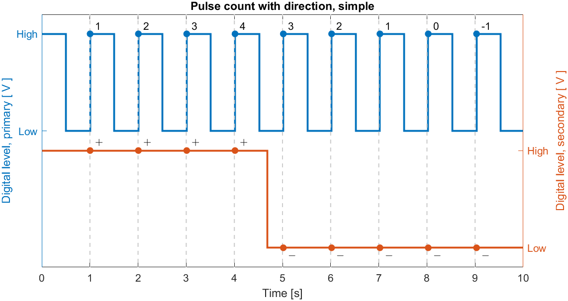
Encoder mode pulse counting with simple direction signal.
Example 2
Below example demonstrates how the CANmod.input can be configured for pulse counting with direction given a very typical output from a rotary encoder.
Rotary encoders often output two phase-shifted pulse signals (from here called Signal A and Signal B). The phase between the two signals depend on the rotation direction, e.g.:
Clockwise rotation: Signal A leads Signal B by 90°
Counter-clockwise rotation: Signal A lags Signal B by 90°
One encoder output signal is connected to the primary channel and the other to the secondary channel (swap to change direction).
The result is illustrated in below figure.
Initially, the direction signal (secondary channel) is high whenever the pulse signal (primary channel) transitions from low to high (increasing the count).
Later, the phase changes, such that the direction signal is low whenever the pulse signal transitions from low to high (decreasing the count).
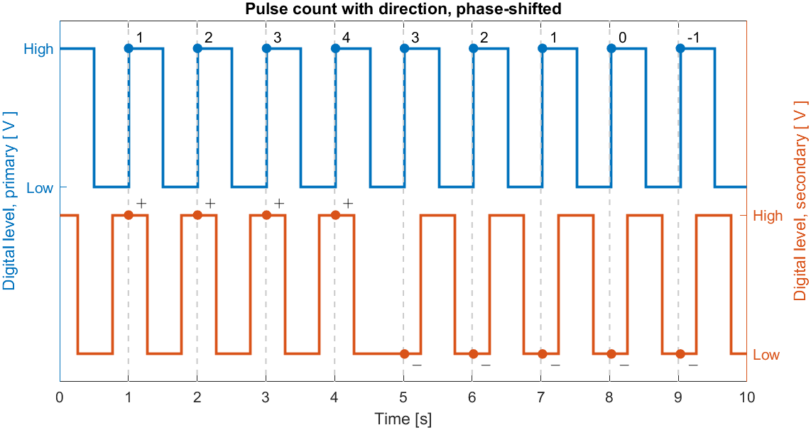
Encoder mode pulse counting with phase-shifted direction signal.
Count
The CANmod.input supports the following pulse count settings:
Reset
When configured to Reset, the channel pulse count is reset each time an output result is produced. The count period is changed by changing the output message scaler (see pulse output configuration).
Example 1
Below illustrates pulse count with 1 s reset (the pulse count output message is set to 1 s period). The frequency of the input pulse signal is 10 Hz. With a 1 s reset, the pulse count directly becomes the input signal frequency in Hz.
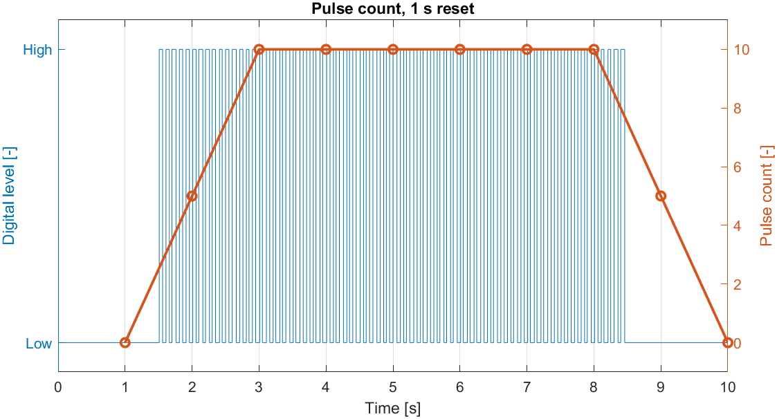
Example of pulse count with 1 s reset. The blue line is the digitized signal. The red line is the pulse count with reset.
Accumulate
When configured to Accumulate, the channel pulse count is never reset. This allows the CANmod.input to be used as a digital counter with adjustable high/low levels. This can e.g. be used to count number of rotations from an inductive pickup sensor or events from a physical switch.
Note
The size of the internal counter is signed 32 bit (approximately ±2 billion).
Example
Below illustrates pulse count configured to accumulate. The frequency of the input pulse signal is 10 Hz. The output message period is 1 s.
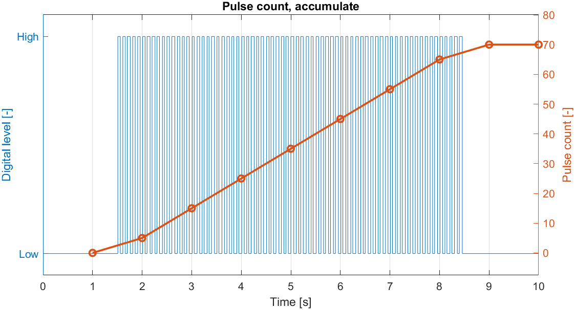
Example of pulse count accumulating. The blue line is the digitized signal. The red line is the accumulated pulse count.
Demo
Below follows a practical demonstration using the CANmod.input to measure the position and speed of a DC-motor output shaft.
Specifically, the demo is based on a combined 12 V DC-motor, gearbox and shaft encoder (MPN EMG30). The encoder consists of two hall-sensors physically positioned such that the pulse outputs are phase-shifted ±90° (depending on direction). The encoder is connected to the CANmod.input as listed below:
Encoder pin # |
Encoder function |
CANmod.input pin # |
CANmod.input function |
|---|---|---|---|
2 |
Hall sensor A out |
11 (channel 2, sig) |
Direction signal |
1 |
Hall sensor B out |
25 (channel 1, sig) |
Pulse signal |
4 |
Hall sensor VCC |
24 (channel 1, +) |
Excitation signal + |
3 |
Hall sensor GND |
12 (channel 1, -) |
Excitation signal - |
Note
The power requirement of the hall-sensor is minimal, making it possible to power directly using the channel 1 excitation signal (~3.3 V).
The hall-sensor outputs are of open-drain type. To be able to generate a positive voltage, both outputs are connected to Hall sensor VCC through 10 kΩ resistors. As a result, the encoder output signal ranges become 0-3.3 V. The CANmod.input analog range is configured to 0-5 V (best possible match without saturating the measurement). With an input range of 0-5 V, the low and high digital thresholds are set to 20% (1 V) and 40% (2 V) respectively.
Below figure shows analog measurements of the two sensor outputs with 0-5 V input ranges and the configured digital thresholds.
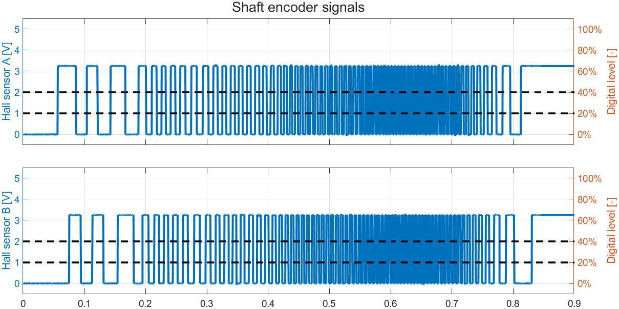
Example of hall-sensor outputs when the motor shaft rotates.
The pulse mode of channel 1/2 is set to encoder. The pulse count is set to accumulate for channel 1 and reset for channel 2. The Pulse 32-bit (ch 1-2, 8 byte) output is enabled and scaled by 100 to generate one output each 100 ms.
An example of the CANmod.input output with the shaft rotating both ways is illustrated below.
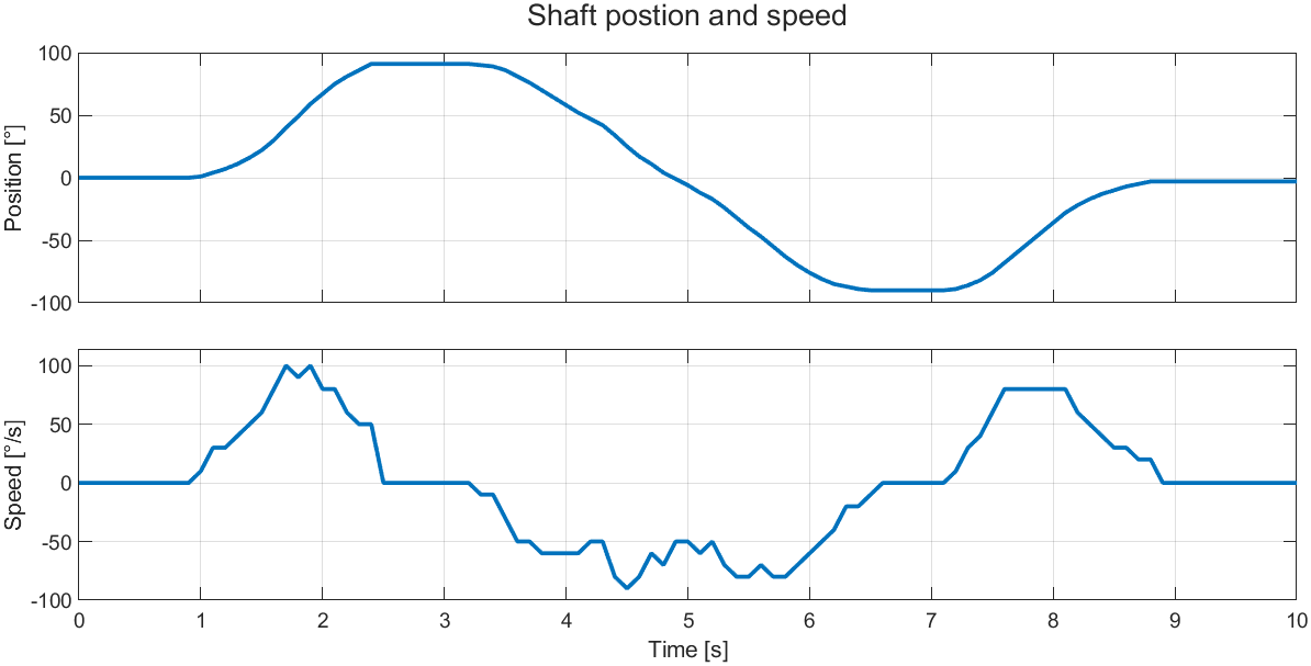
Example of the CANmod.input output with the shaft rotating both directions. The top plot shows shaft position in degrees (pulse accumulate with direction). The bottom plot shows shaft speed in degrees per second[1] (pulse reset with direction).