Explained, analog
This section describes the channel configuration related to analog signals.
Range
The input range can be configured for each channel pair (primary and secondary). The CANmod.input supports the following ranges:
Range [V] |
Resolution [mV/bit] |
|---|---|
0-10 |
9.8 |
0-5 |
4.9 |
0-2.5 |
2.4 |
0-1.25 |
1.2 |
0-0.625 |
0.6 |
Note
The digital resolution can be improved by selecting an input range matching the expected input waveform (see example below)
Example 1
Below illustrates a 0-1 V, 100 mHz sine sampled using 0-10 V and 0-1.25 V input Range respectively. As the waveform is always in range 0-1 V, the Range can be set to 0-1.25 V without risk of clipping. By reducing the input range, the quantization resolution is improved.
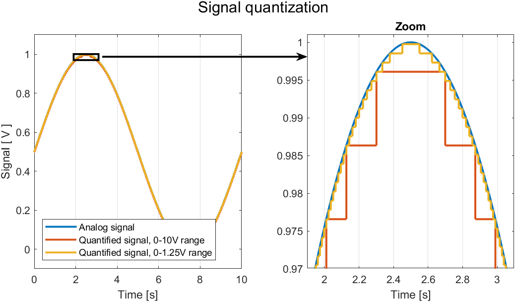
Compares a continuous signal with two quantified signals (using 0-10 V and 0-1.25 V input ranges). The right plot zooms in on the signal to illustrate how the quantization resolution is improved.
Example 2
A typical application is pulse counting generated by a passive inductive pick-up sensor. The input signal amplitude varies with frequency, making it difficult to set digital thresholds. By first amplifying (and potentially saturating) the signal (using the input Range setting), digitization becomes simpler.
Below illustrates a 0-2 V periodic signal sampled using each of the possible Range settings. As the input range is lowered, the signal is effectively amplified. Amplification (even with saturation and clipping) can in some cases be advantageous when a signal is to be digitized. Notice how the “0-0.625” almost becomes a perfect square signal.
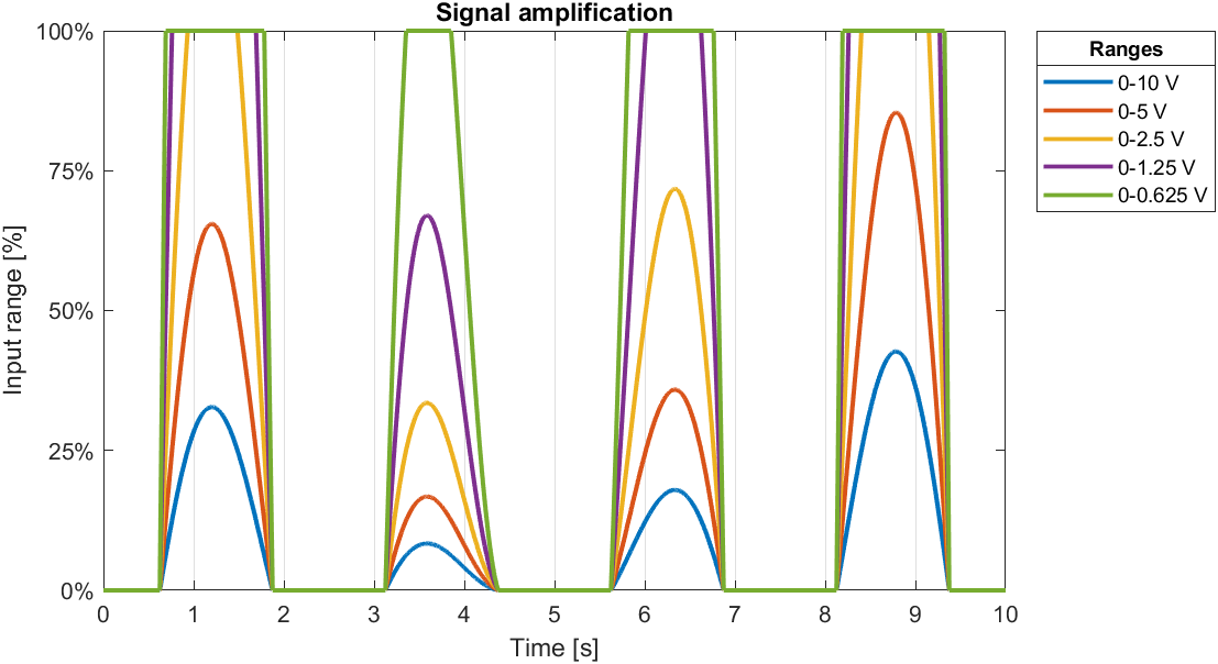
An input signal is amplified using the Range setting.
Note
Using the internal gain amplifier to saturate an input signal does not damage the device.