Explained, digital
This section describes the channel configuration related to digital signals.
Digital low voltage level
Sets the digital low voltage level as a percentage of the full Range. The input signal is considered low when below this threshold.
The threshold is used to generate the digital and pulse output results.
For a example of using the low voltage level, see below.
Digital high voltage level
Sets the digital high voltage level as a percentage of the full Range. The input signal is considered high when above or equal to this threshold.
The threshold is used to generate the digital and pulse output results.
Note
A dead-zone (hysteresis) can potentially improve results for some input waveforms.
Example
Below illustrates the use of the digital high/low voltage level thresholds. The input signal is a 0-10 V, 500 mHz sine. The digital high/low levels are set to 80% (8 V) and 20% (2 V) respectively. The resulting digital level interpretation is given on the right axis.
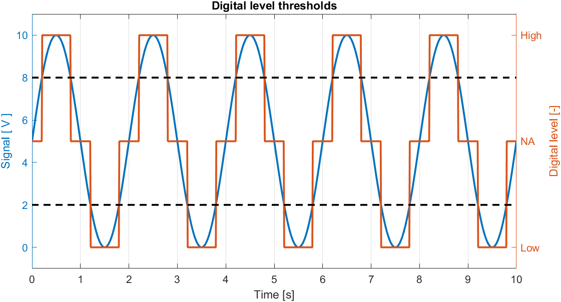
Example of how an analog signal is digitized using the digital high/low voltage level thresholds.