Filter
This page documents the filter configuration.
Configuration file fields
This section is autogenerated from the Rule Schema file.
Receive filters phy.can_s1.filter
List of receive filters. A message is accepted if it passes one or more filters.
Type |
Min items |
Max items |
|---|---|---|
array |
1 |
32 |
Item phy.can_s1.filter.item
Name phy.can_s1.filter.item.name
Filter name (optional).
Type |
Max length |
|---|---|
string |
16 |
State phy.can_s1.filter.item.state
Disabled filters are ignored.
Type |
Default |
Options |
|---|---|---|
integer |
1 |
Disable: |
ID format phy.can_s1.filter.item.id_format
Filter identifier format. Filters apply to messages with matching identifier format.
Type |
Default |
Options |
|---|---|---|
integer |
0 |
Standard (11-bit): |
Frame format phy.can_s1.filter.item.frame_format
Filter frame format. Filters apply to messages with matching frame format.
Type |
Default |
Options |
|---|---|---|
integer |
0 |
Standard: |
ID (HEX) phy.can_s1.filter.item.f1
Filter identifier.
Type |
Default |
|---|---|
string |
0 |
Mask (HEX) phy.can_s1.filter.item.f2
Filter mask.
Type |
Default |
|---|---|
string |
7FF |
Prescaling type phy.can_s1.filter.item.prescaler_type
Filter prescaling type. Prescale by message count, time or data. Select None to disable prescaling.
Type |
Default |
Options |
|---|---|---|
integer |
0 |
None: |
Configuration explained
In below the filter configuration is explained in detail.
Filter tester
During configuration of filters, it is convenient to be able to test if a message passes a specific filter. Below tester can be used to check if a message is accepted or rejected by a filter.
Note
Filter ID, Filter Mask, and Message ID are entered as hexadecimal values. The tester assumes that ID-format of the filter and the message matches (that they are both standard or both extended).
Filter processing
The filter elements in the list of filters are processed sequentially starting from the first element. Processing stops on the first filter match or when the end of the filter list is reached. The filter list supports up to 32 filter elements.
Example: A message matches filter element 3. Filter element 4 is not evaluated.
Messages matching no filters are rejected as default.
Note
The default Configuration File contains filters accepting all incoming CAN messages
Filter name
Filters can be assigned a optional name. The name is not used when processing a filter.
Filter state
The state of filter elements can be Enable or Disable. Disabled filter elements are ignored, as if they are not in the list of filters. If there are no enabled filters in the list then all messages are rejected.
By disabling a filter element (instead of deleting the element) it can be easily enabled at a later time.
Filter ID format
A filter can only match with messages using the same ID format. Standard (11-bit) ID filters can match standard ID messages and extended (29-bit) ID filters can match extended ID messages.
Filter ID / mask
The Filter ID and mask define how a filter is compared to a message ID. A message is accepted by a filter if the following condition is true (try using the filter tester)[1]:
filter_id & filter_mask == message_id & filter_mask
Below provides some practical examples of filters.
Note
The examples uses a mixture of binary (base 2), decimal (base 10) and hexadecimal (base 16) numbers.
Example: Filter configuration which accepts one specific message ID: \(2000_{10} = 11111010000_2\). The filter ID is set to the value of the message ID to accept. The filter mask is set to all ones, such that all bits of the filter are considered, as given in (1).
To test if the message passes the filter, we apply the filter mask to the message ID as given in (2). The masked filter and the masked ID are equal - the message matches the filter.
Example: Filter configuration which accepts two message IDs:
\(2000_{10} = 11111010000_2\)
\(2001_{10} = 11111010001_2\)
Note that the two binary numbers are identical except for the rightmost bit. To design a filter which accepts both IDs, we can use the mask field to mask out the rightmost bit - such that it is not considered when the filter is applied. In (1) the mask is set such that the rightmost bit is not considered (indicated by red color).
To test if the messages pass the filter, we apply the mask to the message ID \(11111010001_2\) as given in (2). The masked filter and the masked ID are equal - the message matches the filter. Note that both \(11111010000_2\) and \(11111010001_2\) match the filter, as the rightmost bit is not considered by the filter (the rightmost bit is masked out).
Example: J1939 - filter configuration which accepts PGN 61444 (EEC1) messages.
J1939 message frames use 29-bit CAN-IDs. The Parameter Group Number (PGN) is defined by 18 of the 29 bits. The remaining 11 bits define e.g. the priority and source-address of the message. It is often useful to configure a filter to accept a specific PGN while ignoring the remaining 11 bits - this can be done using the filter mask.
Below, the left red bits represent the 3-bit priority, the green bits the 18-bit PGN and the right red bits the 8-bit source address of the 29-bit CAN-ID.
Message ID bits in positions with zero bits in the filter mask are ignored. By using \(\text{3FFFF00}_{16}\) as filter mask, the priority and source are ignored.
To specifically accept PGN 61444 (\(\text{F004}_{16}\)) messages, the message ID is set to \(\text{F00400}_{16}\) - note the the final 8-bit \(\text{00}_{16}\) represents the source address which is ignored by the filter mask (these bits can be any value).
Filter mask \(\text{3FFFF00}_{16}\) can be used for all J1939 PGN (PDU2) messages. To accept specific PGNs, the message ID is adjusted. To accept one specific PGN (as in the example above), the message ID is set to the specific PGN with \(\text{00}_{16}\) appended to represent the ignored source address field.
Message Prescaling
Message prescaling can be used to reduce the number of received messages for a given message ID. Prescaling is applied to the messages accepted by the associated filter. The list of filters can be assigned a mixture of prescaler types.
The prescaling type can be set to:
None: Disables prescalingCount: Prescales based on message occurrencesTime: Prescales based on message period timeData: Prescales based on changes in the message data payload
The first message with a given ID is always accepted regardless of prescaling type.
Note
A maximum of 100 unique message IDs can be prescaled for each CAN-bus channel (the first 100 IDs received by the CANmod.router). Additional unique IDs are not prescaled
Count
Count prescaling reduces the number of messages with a specific ID by a constant factor (prescaling value). A prescaling value of 2 accepts every 2nd message (with a specific ID), a value of 3 every 3rd and so on up to 256[2].
Example: Count prescaling applied to ID \(600_{10}\) with a scaling value of 3.
ID (DEC) |
ID occurrences |
Result |
|---|---|---|
\(600_{10}\) |
1 |
Accept |
\(600_{10}\) |
2 |
Reject |
\(600_{10}\) |
3 |
Reject |
\(600_{10}\) |
4 |
Accept |
\(600_{10}\) |
5 |
Reject |
Time
Time prescaling sets a lower limit on the time interval (period time) of a specific message ID. This is done by rejecting messages until at least the prescaler time has elapsed[3]. The prescaler timer is reset each time a message is accepted. The prescaling value is set in milliseconds[4] with a valid range 1-4194304 (0x400000).
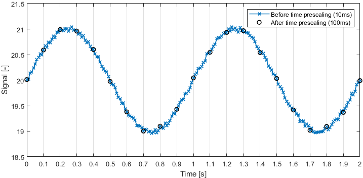
This prescaler type is e.g. useful if a slowly changing signal (low frequency signal content) is broadcasted on the CAN-bus at a high frequency[5].
Example: A slowly changing temperature measurement broadcasted every 10 ms (100Hz). Prescaled to a minimum time interval of 100ms (prescaler value set to 100).
Example: Time prescaling applied to ID \(700_{10}\) with a time interval of 1000ms.
ID (DEC) |
Message timestamp [ms] |
Prescaler timer [ms] |
Result |
|---|---|---|---|
\(700_{10}\) |
200 |
0 |
Accept |
\(700_{10}\) |
700 |
500 |
Reject |
\(700_{10}\) |
1000 |
800 |
Reject |
\(700_{10}\) |
1200 |
1000 -> 0 (reset) |
Accept |
\(700_{10}\) |
1300 |
100 |
Reject |
\(700_{10}\) |
3200 |
2000 -> 0 (reset) |
Accept |
\(700_{10}\) |
4200 |
1000 -> 0 (reset) |
Accept |
\(700_{10}\) |
5200 |
1000 -> 0 (reset) |
Accept |
Data
Data prescaling can be used to only accept messages when the data payload changes. A mask can be set to only consider changes in one or more specific data bytes. The mask works on a byte level. The mask is entered in hex up to 8 bytes long (16 hex characters). Each byte contains 8 bits, allowing for the mask to be applied to any of the maximum 64 data bytes (CAN FD).
This prescaler can be used to only receive a message when a part of the payload has changed.
Examples of data masks:
"": An empty mask triggers on any data change (equivalent to mask valueFFFFFFFFFFFFFFFF)1: Triggers on changes to the first data byte (binary1)2: Triggers on changes to the second data byte (binary10)3: Triggers on changes to the first or second data byte (binary11)9: Triggers on changes to the first or fourth data byte (binary1001)FF: Triggers on changes to any of the first 8 data bytes (binary11111111)100: Triggers on changes to the 9th data byte (binary100000000)
If the data payload contains more data bytes than entered in the mask, then changes to the additional bytes are ignored by the prescaler.
Warning
Data prescaling assumes that a the payload length of a specific message ID is constant
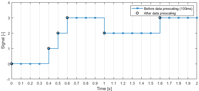
Example: A discretely changing signal is broadcast every 100 ms (10Hz). A data prescaler is used such that only changes in the signal are received.
Example: Data prescaling applied to ID \(800_{10}\) with empty mask (all changes considered). D0-D3 is a 4-byte payload (with D0 the first data byte).
ID (DEC) |
D0 |
D1 |
D2 |
D3 |
Result |
|---|---|---|---|---|---|
\(800_{10}\) |
00 |
11 |
22 |
33 |
Accept |
\(800_{10}\) |
00 |
11 |
22 |
33 |
Reject |
\(800_{10}\) |
00 |
BB |
22 |
33 |
Accept |
\(800_{10}\) |
AA |
BB |
22 |
33 |
Accept |
\(800_{10}\) |
AA |
BB |
22 |
DD |
Accept |
\(800_{10}\) |
AA |
BB |
22 |
DD |
Reject |
Example: Data prescaling applied to ID \(800_{10}\) with mask 1 (considering only changes to the 1st data byte). D0-D3 is a 4-byte payload (with D0 the first data byte).
ID (DEC) |
D0 |
D1 |
D2 |
D3 |
Result |
|---|---|---|---|---|---|
\(800_{10}\) |
00 |
11 |
22 |
33 |
Accept |
\(800_{10}\) |
00 |
11 |
22 |
33 |
Reject |
\(800_{10}\) |
00 |
BB |
22 |
33 |
Reject |
\(800_{10}\) |
AA |
BB |
22 |
33 |
Accept |
\(800_{10}\) |
AA |
BB |
22 |
DD |
Reject |
\(800_{10}\) |
AA |
BB |
22 |
DD |
Reject |
Example: Data prescaling applied to ID \(800_{10}\) with mask 8 (considering only changes to the 4th data byte). D0-D3 is a 4-byte payload (with D0 the first data byte).
ID (DEC) |
D0 |
D1 |
D2 |
D3 |
Result |
|---|---|---|---|---|---|
\(800_{10}\) |
00 |
11 |
22 |
33 |
Accept |
\(800_{10}\) |
00 |
11 |
22 |
33 |
Reject |
\(800_{10}\) |
00 |
BB |
22 |
33 |
Reject |
\(800_{10}\) |
AA |
BB |
22 |
33 |
Reject |
\(800_{10}\) |
AA |
BB |
22 |
DD |
Accept |
\(800_{10}\) |
AA |
BB |
22 |
DD |
Reject |
Example: Data prescaling applied to ID \(800_{10}\) with mask 9 (considering only changes to the 1st or 4th data byte). D0-D3 is a 4-byte payload (with D0 the first data byte).
ID (DEC) |
D0 |
D1 |
D2 |
D3 |
Result |
|---|---|---|---|---|---|
\(800_{10}\) |
00 |
11 |
22 |
33 |
Accept |
\(800_{10}\) |
00 |
11 |
22 |
33 |
Reject |
\(800_{10}\) |
00 |
BB |
22 |
33 |
Reject |
\(800_{10}\) |
AA |
BB |
22 |
33 |
Accept |
\(800_{10}\) |
AA |
BB |
22 |
DD |
Accept |
\(800_{10}\) |
AA |
BB |
22 |
DD |
Reject |