Digital (ch 1-8, 1 kHz, 4 byte)
The digital output contains a digital interpretation of the observed waveform. The waveform is digitized according to the configured thresholds.
When scaling is used (>1), the High and Low signals can be used as level detectors when the digital output frequency is scaled. This can e.g. be used to capture brief events even when configured to produce a low frequency digital output.
Configuration file fields
This section is autogenerated from the Rule Schema.
Digital, channel 1-8 (1 ms) output.digital_1_8
State output.digital_1_8.state
Type |
Default |
Options |
|---|---|---|
integer |
1 |
Disable: |
ID Format output.digital_1_8.id_format
ID format of the message
Type |
Default |
Options |
|---|---|---|
integer |
0 |
Standard (11-bit): |
Message ID (hex) output.digital_1_8.id
ID of the message in hex. Example: 00435354.
Type |
Default |
|---|---|
string |
01 |
Trigger method output.digital_1_8.trigger
Transmission trigger method. Push: Signal is periodically transmitted. Poll: Signal is transmitted on request
Type |
Default |
Options |
|---|---|---|
integer |
0 |
Push: |
Frame layout
The frame layout is defined in the CANmod.input DBC file.
Each digital signal (X) contains the following values:
DigitalXAct: Actual digital levelDigitalXHgh: High since previous outputDigitalXLow: Low since previous output
The values are explained in more detail below.
DigitalXAct
The Actual signal outputs the most recent digital level.
The signal can take one of the following values:
0: NA / unknown
1: Low
2: High
DigitalXHgh
The High (hgh) signal outputs if at least one high level was detected during the output period (see example below).
The signal can take one of the following values:
0: No (high level not detected)
1: Yes (high level detected)
DigitalXLow
The Low (low) signal outputs if at least one low level was detected during the output period (see example below).
The signal can take one of the following values:
0: No (low level not detected)
1: Yes (low level detected)
Example
In this example, the digital output is configured to Push and scaled by 5. As a result, a digital output message is generated each 5 ms (1000 kHz / 5 = 200 Hz = 5 ms). Each generated output is based on 5 samples. Below Figure illustrates how a waveform is sampled (and digitized). The Actual, High and Low signals of each output period become:
Output period 1
Actual: High
High: Yes
Low: Yes
Output period 2
Actual: Low
High: No
Low: Yes
Output period 3
Actual: Unknown
High: Yes
Low: No
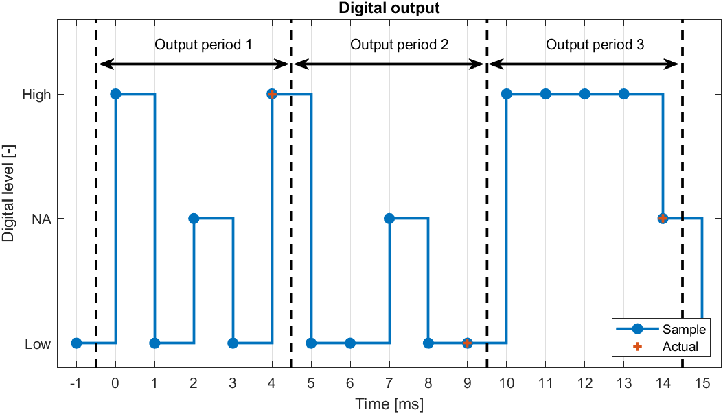
Example of 3 digital output periods. Each period contains 5 samples. The Actual (most recent) sample is marked.