Installation
This section outlines the installation requirements that shall be satisfied.
Supply quality
The nominal voltage shall be kept within specifications at all times. The device is internally protected against low energy voltage events which can be expected as a result of supply wire noise, ESD and stub-wire inductance.
If the supply line is shared with inductive loads, care should be taken to ensure high energy voltage events do not reach the device. Automotive environments often include several sources of electrical hazards, such as load dumps (disconnection of battery while charging), relay contacts, solenoids, alternator, fuel injectors etc. The internal protection circuitry of the device is not capable of handling high energy voltage events directly from such sources.
Grounding
ISO 11898-2 tolerates some level of ground offset between nodes. To ensure the offset remains within range, it is recommended to use a single point ground reference for all nodes connected to the CAN-bus. This may require the ground wire to be carried along with data wires.
If a secondary CAN-bus network is connected to Channel 2, care must be taken to ensure that the ground potentials of the two networks can safely be connected through the common ground in the device.
Cable shielding
Shielding is not needed in all applications. If shielding is used, it is recommended that a short pig-tail be crimped to the shield end at each connector.
CAN ISO 11898-2
ISO 11898-2 defines the basic physical requirements of a high-speed CAN-bus network. Some of these are listed below:
Max line length (determined by bit-rate)
Line termination (120 ohm line termination at each end of data line)
Twisted data lines
Ground offsets in range -2V to +7V
CAN-bus stub length
It is recommended that the CAN-bus stub length is kept short. The stub length is defined as the length from the ”main” data line wires to the connection point of the CAN-bus nodes.
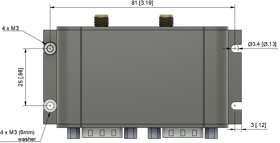
Mounting
The device should be mounted in a way that minimizes vibration exposure and accounts for the IP-rating of the device.
Hardware version \(\ge\) 00.03 uses flanges for easy and robust mounting. The flanges are designed for 4 x M3 screws and 4 x 6 mm washers.