Control
This page documents the control configuration
Configuration file fields
This section is autogenerated from the Rule Schema file.
Control can.control
Control signal
Control reception (rx) state can.control.control_rx_state
Control CAN-bus reception state (including logging)
Type |
Default |
Options |
|---|---|---|
integer |
0 |
Disable: |
Control transmission (tx) state can.control.control_tx_state
Control CAN-bus transmission state (including logging)
Type |
Default |
Options |
|---|---|---|
integer |
0 |
Disable: |
Start can.control.start
Message can.control.start.message
Channel can.control.start.message.chn
CAN-bus channel
Type |
Default |
Options |
|---|---|---|
integer |
0 |
CAN-internal: |
ID-format can.control.start.message.id_format
ID-format of message.
Type |
Default |
Options |
|---|---|---|
integer |
0 |
Standard (11-bit): |
ID (hex) can.control.start.message.id
ID of message in hex. Example: 1FF.
Type |
Default |
|---|---|
string |
0 |
ID mask (hex) can.control.start.message.id_mask
ID mask in hex. Example: 7FF.
Type |
Default |
|---|---|
string |
7FF |
Signal can.control.start.signal
Signal type can.control.start.signal.type
Type |
Default |
Options |
|---|---|---|
integer |
0 |
Unsigned: |
Signal byteorder can.control.start.signal.byteorder
Can be Motorola (big endian) or Intel (little endian)
Type |
Default |
Options |
|---|---|---|
integer |
1 |
Motorola: |
Signal bit position can.control.start.signal.bitpos
Type |
Default |
Minimum |
Maximum |
|---|---|---|---|
integer |
0 |
0 |
512 |
Signal bit length can.control.start.signal.length
Type |
Default |
Minimum |
Maximum |
|---|---|---|---|
integer |
0 |
0 |
64 |
Signal scaling can.control.start.signal.factor
Type |
Default |
|---|---|
number |
0 |
Signal offset can.control.start.signal.offset
Type |
Default |
|---|---|
number |
0 |
Trigger high (dec) can.control.start.trigger_high
Type |
Default |
|---|---|
number |
0 |
Trigger low (dec) can.control.start.trigger_low
Type |
Default |
|---|---|
number |
0 |
Stop can.control.stop
Message can.control.stop.message
Channel can.control.stop.message.chn
CAN-bus channel
Type |
Default |
Options |
|---|---|---|
integer |
0 |
CAN-internal: |
ID-format can.control.stop.message.id_format
ID-format of message.
Type |
Default |
Options |
|---|---|---|
integer |
0 |
Standard (11-bit): |
ID (hex) can.control.stop.message.id
ID of message in hex. Example: 1FF.
Type |
Default |
|---|---|
string |
0 |
ID mask (hex) can.control.stop.message.id_mask
ID mask in hex. Example: 7FF.
Type |
Default |
|---|---|
string |
7FF |
Signal can.control.stop.signal
Signal type can.control.stop.signal.type
Type |
Default |
Options |
|---|---|---|
integer |
0 |
Unsigned: |
Signal byteorder can.control.stop.signal.byteorder
Can be Motorola (big endian) or Intel (little endian)
Type |
Default |
Options |
|---|---|---|
integer |
1 |
Motorola: |
Signal bit position can.control.stop.signal.bitpos
Type |
Default |
Minimum |
Maximum |
|---|---|---|---|
integer |
0 |
0 |
512 |
Signal bit length can.control.stop.signal.length
Type |
Default |
Minimum |
Maximum |
|---|---|---|---|
integer |
0 |
0 |
64 |
Signal scaling can.control.stop.signal.factor
Type |
Default |
|---|---|
number |
0 |
Signal offset can.control.stop.signal.offset
Type |
Default |
|---|---|
number |
0 |
Trigger high (dec) can.control.stop.trigger_high
Type |
Default |
|---|---|
number |
0 |
Trigger low (dec) can.control.stop.trigger_low
Type |
Default |
|---|---|
number |
0 |
Configuration explained
This section contains additional information and examples.
The control signal can be used to control message reception (i.e. logging) and / or message transmission (e.g. processing of the transmit list) for each CAN-bus channel. The control signal has a flexible configuration allowing for integration with many protocols. The control signal can e.g. be used to start / stop logging based on some application parameters, such as speed, RPM, geofence, time-of-day or discrete events.
Note
The control-signals can trigger on Internal signals such as TimeCalendar (e.g. log only from 08:00 to 16:00)
The configuration of the signals uses a concept similar to that used by .DBC files. In case a .DBC file is available (describing the interpretation of the control message signals), the information from the file can be used directly for configuration. For more information see Section Signal.
Control signal overview:
A control signal can be configured for each CAN-bus channel
A control signal can be based on messages from any channel
One message ID is used for start and one for stop. These can be different or the same
The message payload is decoded on the device, making it easy to set start / stop ranges
The start / stop ranges follow the following logic:
If the start / stop ranges do not overlap, they are evaluated individually
If the start range lies within the stop range, then start takes precedence (see examples below)
If the stop range lies within the start range, then stop takes precedence (see examples below)
Note
File splitting is not affected by the control signal (i.e. the control signal does not force additional log file splits)
Note
The control signal can only be used if accepted by the CAN-bus filter
Note
The initial states of message reception and transmission are set in configuration section General.
Examples
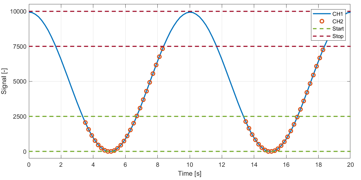
Example: Start / stop ranges not overlapping.
Can e.g. be used to start logging when speed signal exceeds some value and stop when it drops below some other value.
Start trigger:
High: 10000
Low: 7500
Stop trigger:
High: 2500
Low: 0
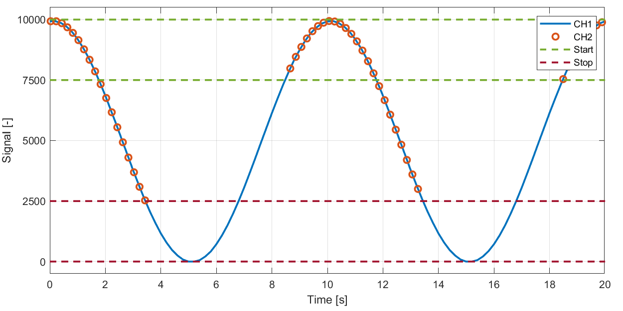
Example: Start / stop ranges not overlapping.
Can e.g. be used to start logging when pressure signal drops below some value and stop when it again raises above some other value.
Start trigger:
High: 2500
Low: 0
Stop trigger:
High: 10000
Low: 7500
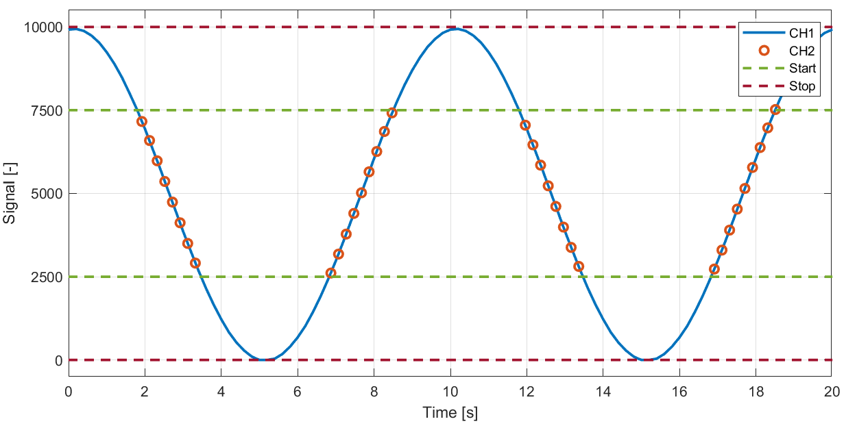
Example: Start range lies within stop range, start takes precedence.
Can e.g. be used to start logging when a temperature signal lies within some range and stop when outside.
Start trigger:
High: 7500
Low: 2500
Stop trigger:
High: 10000
Low: 0
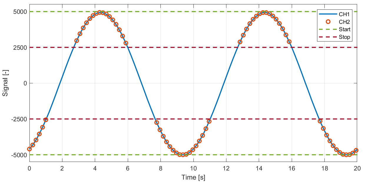
Example: Stop range lies within start range, stop takes precedence.
Can e.g. be used to start logging when the absolute value of an acceleration signal exceeds a certain value.
Start trigger:
High: 5000
Low: -5000
Stop trigger:
High: 2500
Low: -2500