Alignment
This page documents the alignment configuration.
Configuration file fields
This section is autogenerated from the Rule Schema file.
IMU-mount alignment gnss.alignment
IMU-mount alignment configuration. During normal operation, alignment angles must be set manually. During setup, the device can in some cases help estimate the angles. While configured to estimate angles, all other GNSS/IMU outputs are disabled. For more information see the user manual.
Method gnss.alignment.method
Type |
Default |
Options |
|---|---|---|
integer |
0 |
Manual: |
Z angle (0 to 360) gnss.alignment.z
Type |
Default |
Minimum |
Maximum |
|---|---|---|---|
integer |
0 |
0 |
360 |
Y angle (-90 to 90) gnss.alignment.y
Type |
Default |
Minimum |
Maximum |
|---|---|---|---|
integer |
0 |
-90 |
90 |
X angle (-180 to 180) gnss.alignment.x
Type |
Default |
Minimum |
Maximum |
|---|---|---|---|
integer |
0 |
-180 |
180 |
Configuration explained
This section contains additional information and examples.
The GNSS/IMU module uses an internal IMU coordinate system. The alignment configuration can be used to virtually rotate the device, such that the IMU coordinate aligns with the application (e.g. car, boat, plane, etc.) - making it easier to interpret the data generated by the IMU.
When specifically installed in a vehicle[1], the device assumes a specific application coordinate system. This specific coordinate system is denoted the vehicle coordinate system. Aligning the IMU and vehicle coordinate systems is required when using sensor-fusion. The device can help estimate the rotation needed to align the two coordinate systems (see Method).
Below figures define the IMU and vehicle coordinate systems. Both coordinate systems are right-handed with the Z-axis pointing up.

IMU coordinate system (device top view) |

Vehicle coordinate system (vehicle top view) |
Method
The device supports two alignment methods:
ManualEstimate
Manual
Using the Manual alignment method, the alignment angles are provided and entered by the user. The device applies these alignments (rotations) to virtually rotate the device. The alignment is entered as Z/Y/X alignments, see Alignment Z/Y/X.
Estimate
When installed in a vehicle[1], the device can help estimate the alignment angles (rotations) needed to align the IMU and vehicle coordinate systems. To be able to complete the estimation, the vehicle needs to undergo sufficient dynamics.
When active, the device generates an additional output (see ImuAlign signals) including the progress of the estimation. The estimation is completed once the algorithm has sufficient confidence in the estimated alignment angles. When completed, the resulting alignment estimates can be noted down and entered using the manual alignment method.
The recommended test sequence is:
Install device in a fixed position in the vehicle
Turn on device and wait for very good GNSS signal (wait 1-3 minutes)
Perform a test drive with at least 10 right turns and 10 left turns (each preferably 90° or more)
Turn off device, extract log file(s) and decode (see Internal signals) to obtain estimation results
See Example 2 (estimate) for an example on how to interpret the results.
Note
All other GNSS/IMU outputs are disabled when the estimate method is enabled.
Alignment Z/Y/X
The Z, Y and X alignment angles represent the Euler-angles required to rotate the application coordinate system to the IMU coordinate system. It is generally up to the user to define the application coordinate system. When specifically installed in a vehicle[1], the application coordinate system becomes the vehicle coordinate system (see Configuration explained).
If multiple angles are misaligned, then the Z rotation should be performed first, then the Y rotation and finally the X rotation.
Warning
It is recommended to physically install the device such that no more than a single angle is misaligned. Configuring multiple misaligned angles is difficult. If installed in a vehicle[1] and multiple misalignments cannot be avoided, consider using the Estimate method.
Example 1 (manual)
The device is installed in a vehicle[1] with the IMU and vehicle coordinate systems not aligned as illustrated in the left Figure. The alignment angles required, to align the two coordinate systems, are determined by imagining that the vehicle coordinate system is rotated such that it becomes oriented as the IMU coordinate system.
In this example, only alignment of Z is required. Below right Figure illustrates how the vehicle coordinate system is rotated by -30° to align with the IMU coordinate system.
As defined in the Configuration file fields, the valid range of the Z angle specifically is \({0}^\circ-{360}^\circ\). To configure a Z misalignment angle of \(-{30}^\circ\), we calculate the equivalent angle to \({360}^\circ-{30}^\circ={330}^\circ\).

Orientation |

Alignment |
The resulting configuration becomes:
"alignment": {
  "method": 0,
  "z": 330,
  "y": 0,
  "x": 0
}
Example 2 (estimate)
In this example, the device is physically installed in a vehicle with an orientation roughly equal to the one illustrated in Example 1, i.e. placed flat with a Z-angle of \(\approx{330}^\circ\).
The alignment Method is set to Estimate and the recommended test sequence is completed.
The results generated by the device (see ImuAlign signals) are illustrated below (note that it is not necessary to plot these to use the result).
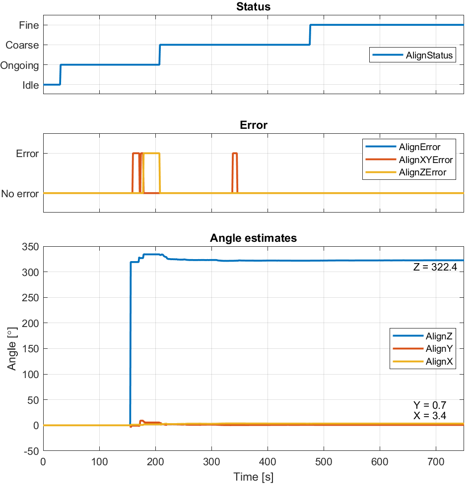
The trace legends refer directly to the signal names, see ImuAlign signals.
After a little less than 500 seconds, the estimation algorithm reaches high confidence in the estimated angles (status becomes Fine). At this point, the resulting angle estimates can be noted down and entered in the configuration file as manually entered alignment angles (closest integer values).
The resulting configuration becomes:
"alignment": {
  "method": 0,
  "z": 322,
  "y": 1,
  "x": 3
}